Lesson 6: Part 1: USART - Transmitting Data Out To PC

To expand the capability of the embedded system, a communication channel is always require. For example, to communicate with a PC, usually a Serial Port (RS232) will be use. Machine to machine communication usually is realise using RS232 or RS485/RS422 (longer distance). In embedded system, the peripheral that incharge of such function is UART(Universal asynchronous receiver transmitter) or USART (Universal synchronous asynchronous receiver transmitter)

As Debugging Tool

One useful usage of USART is in debugging. But inserting code that print debugging message, we can always know what is the value of variable, which part of the code MCU is running. Sometimes, it is more efficient by looking at the debug message instead of stepping through the program.

The down side of this is that a dedicated buffer has to be allocated to keep the debugging buffer(as sending USART speed is slow).

Physical Connection

USB To Serial Port < --> Max232 <--> USART/UART

In this tutorial, we will be looking at enabling communication between STM32F030 with PC through RS232. We will be enabling USART1 on MCU part. To enable communication with PC, an additional voltage converter(MAX232 chipset) circuit is require as shown below:

RS232 Circuit
The above image is take from here. It also include a good introduction of interfacing with PC.

Currently most of the PC/laptop no longer come with DB-9 Serial Port. And a replacement of this would be a USB to Serial converter as shown below:
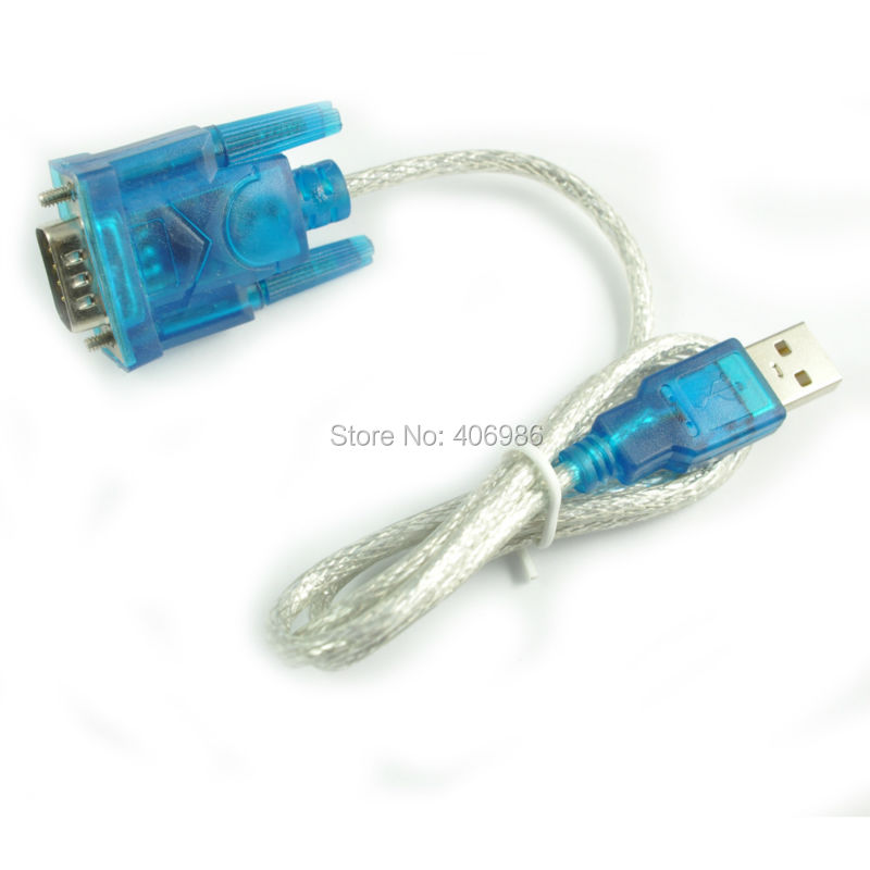
USB to Serial Converter

USB To TTL

The easiest converter to use is shown below, which enabling direct interface into STM32F030, without requiring MAX232 as shown below:
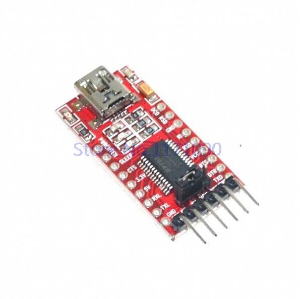
USB to TTL
Enabling direct connection to STM32F030 USART

STM32F030 SFR Configurations

We will be using the following settings on STM32F030:
  • Baud Rate: 115200bps
  • Data bits: 8
  • Stop bits: 1
  • Parity : None
  • Handshake : None
On PC, you can use teraterm, hyperterminal or similar software to open the Serial Port and accept data send from STM32F030. The above settings must be configure in software to ensure proper communication between PC and STM board.

As for the SFR section, it would be too lengthy to go through each of the register. I have heavily comment on the source code instead to provide explanation of each SFR. Refer here for the source code.

Source Code Explained

Below are the key actions implemented in source code to enable data transmission.

1. SFR configurations
  • Enable GPIO block that contain USART TX/RX pn
  •  Configure TX/RX pin to use as USART (so that is will not use as general purpose input/output)
  • Enable USART block
  • USART settings (baud rate, data bits, stop bits, parity, handshake)
  • Enable USART function, and transmit, receive function
2.  Data Transmit Function (call by application)
  • Putting first byte into transmit buffer
  • Waiting first byte transmit complete
  • Putting subsequenct byte into transmit buffer and wait until byte is transmit out. Repeating this until all bytes has been transmit
The example will be continuing printing out message 'Hello World!" through USART1.

Below is the image of my connection, using an USB to TTL device, directly connect to STM32
  • White cable: 3V
  • Blue cable: GND
  • Grey cable: PA9, USART_TX
  • Purple cable: PA10:USART_RX
Physical Connection

Source Code Implementation

The above source code is implementing a blocking transmit. Which means that the MCU will be waiting(a while loop) when current chracter being transmit out. Thus when sending full length of 'Hello World!', no other process can be executed (except ISR). This is inefficient but this is the simpliest way to ensure character transmitting is working.

Apart from blocking transmit, we can also perform USART transmit using:
  • Interrupt: allow interrupt occur when current data has been transfer to transmit buffer(it would take some time to transmit out), so we can load next data into TDR. This is better than blocking, but still require ISR code to loadbuffer into TDR
  • DMA: enabling DMA auto transfer when current data has been transfer to transmit buffer. This is the most efficient method, but also more complex as it involve interrupt + DMA control.
Later stage we shall be looking for DMA method. For now, we should get things work in the simpliest method: blocking transmit/receive.

Lastly, I attached a short video on my capture on data transmit from STM32 on this tutorial.


Lesson 5: Part 2: SysTick Timer - Building Operating System

As promise, we will be doing some real work here, making our first Operating System - task scheduler function.

The task scheduler that perform round-robin with no priority. Each task will have a task timer count which get decrement. And when the timer count reach zero, the task is ready to be executed. There will be no preemptive function and thus each task that executed should not have an infinite loop that occupied CPU time indefinitely. This is just a brief explanation of the task scheduler in action as the main focus here is on the SysTick.

Below is the snapshot of the code on the task scheduler.

Structure Defining Task Called Interval and Task Pointer
SysTick Timer Interrupt That Decrement Task Delay


Called Task Upon Task Delay Timeout
Again, the above complete source code has been uploaded into github.

Lesson 5: Part 1: SysTick Timer - Running it

On ARM architecture, a special peripheral that I appreciated much is this:  a dedicated timer called system tick, which use as system tick for RTOS or task scheduler.

The register settings is much simpler as it is meant to be used as system tick in software. In this tutorial, again, we will be using this timer to toggle the LED. On second thought, lets have some fun instead, lets build a Operating System! Unfortunately, this operating system is only have a round-robin task scheduler.

I shall split this into 2 session, first is a guide to enabling the System Tick. The second tutorial will be putting System Tick into our task scheduler.

Do take note that the system tick description is in the programming manual. In here, I will be setting the system tick to timeout every 100ms. This is too big for normal application, but since I will be running tasks with 1seconds and 2 seconds timeout later on, it is good enough here.

After running so many tutorial, finally I saw some easy guide as below:
Guide On Setting Up SysTick
First is the program reload value. With system clock running at 48MHz, each clock running at 1/48MHz, which is 20.83nS. To get to 100ms, I will need 4800000 tick. This correspond to the reload value that I should use.
SysTick Reload Value:
STK_RVR : 4800000
Next I just need to clear the current value to zero
Clear SysTick Current Count
STK_CVR : 0
And finally configure program control and status register
Setting Control and Status Register
STK_CSR : 0x000007
That's it. A few SFR setting and we are good to go. Just go to github(Lesson5_SysTick_Blinking_LED) to grab the source code. And it seems that I still need the blinking LED in this and next (task scheduler) example. Below is the code snippet on SFR settings.
Source Code To Setup SysTick


Lesson 4: Part 1: Timer: Running A Timer

There is bunch of timer available in STM32F030, below is a snapshot from the F0 series datasheet.

Summary of Timers in ST F0 Series
This is tutorial we will be using TIM3 in our exercise. This timer is select as it is one of the timer that is available across all MCU. Initially I want to use TIM6 as example as it have simpler configurations, but only certain MCU part will this timer and thus I have drop the idea.

To understand TIM3 features and SFR control, refer to ReferenceManual at Chapter 14: General Purpose Timer (TIM3). Frankly speaking, I have quite a hard time in understanding the description, and also having difficulties in finding the register I need. I hope this is not a sign for I am too old for this job, :-)
Reference Manual on TIM3


Before we dive into  controlling the timer, we need some understanding on timers. Some reference is here.

Generally to use a timer, we will need to perform the following actions:
  1. Enable timer 3
  2. Timer interrupt duration calculation
  3. Enable timer interrupt
  4. Run timer
  5. Implement timer ISR

1. Enable Timer 3

This is done by enabling Timer3 block by supplying clock.
Enable Timer 3 Block
RCC_APB1ENR: TIM3_EN

2. Timer Interrupt Duration Calculation

2.1 Timer Prescaler

A timer is just a counter that keep running up/down (count up or count down) until overflow and interrupted is generated due to  the overflow. The counter is increment in a fix duration. A 48MHz system, each clock cycle can increment the counter, making the duration for counter 0->1 happen in 1/48MHz (208.3 nano-seconds)

STM32F030 is running at 48MHz, typically we want a timer to have duration of 1milliseconds. In order to 'scale down' the frequency, we will need the prescaler. Each MCU will have its own prescaler formula as describe in user manual.
Timer Prescaler
TIM3_PSC = 47999
As shown in above, CK_CNT is the frequency that we need, PSC is the prescaler value that we should set in order to obtain the frequence we want.
Said we need 1 micro-seconds interval, that would equal to 1MHz, thus the prescale value = 48MHz/1MHz - 1 = 47
However, in this tutorial I will created a 1 seconds timer, a more appropiate frequency would be 1KHz. Thus, the prescale value = 48MHz/1KHz - 1 = 47999.

As the prescale is only 16 bit, the slowest frequency we can have will be 732.4Hz.

2.2 Timer Auto Reload Value

After setting the prescaler 47999, we now have a counter(timer) that increment every 1milliseconds. We want to have a timer that interrupt at 1 second interval, thus we want the counter to count up to 1000 (1000*1milliseconds = 1 second) and generated an interrupt.

The SFR so use in determining the maximum count is Timer Auto Reload Value.
Timer Auto Reload
TIM3_ARR  = 1000
 We just need to set this register as 1000 to get a 1 seconds timer interrupted. The range we can have here is from 1mS to 65535 mS (base on prescale value of 47999).

By adjusting prescaler and auto-reload register, we can control timer interrupt period to a smaller/larger duration.

3. Enable timer interrupt

We need to enable the following SFR for interrupt generation upon timer overflow
Enable Timer 3 Overflow Generated Interrupt
TIM3_DIER : UIE
Interrupt Block : Enable Timer 3 Interrupt
NVIC_ISER : 16 (16 is ISR for Timer 3) as shown below
Vector Table Showing Timer 3 At Position 16

4. Run timer

Start timer with the following

Enable Timer Run
TIM_CR1 : CEN

5. Implement Timer ISR

Timer ISR is pretty simple, we just need to clear the interrupt flag, so that ISR is not called until next interrupt happen.

Then is our user code, here we just set a flag upon interrupt. In the main loop there will be code that trigger LED-LD3 base on this flag. Do notice the flag is declare as below:
volatile unsigned char LEDOnOff;

A 'volatile' keyword is require here to inform compiler that this variable can be change anytime in the program. This will avoid compiler optimizing the LED trigger code in main function. A detail explanation of these will be out of this tutorial scope. I will try explain on this in other post instead.

As a rule of thumb, variable use in the interrupt should always declare with 'volatile' keyword.

As usual, I have push the tutorial code into github.


Lesson 3: Part 2: Interrupt - More about it

Interrupt is important as it enable software to transfer works to hardware and get notified when the hardware has completed its works. A good example is our previous interrupt tutorial. By passing the input checking to hardware, software no longer require to constantly poll the pin state and check if there is state change.

However, interrupt does make the system more complex in the sense that now any code in the main() function can be interrupted and interrupt service routine(ISR) get executed. Refer below for more explanation of interrupt to avoid buggy software.
  1. Embedded.com

Lesson 3: Part 2: Interrupt - External Input


In this lesson we will be showing way to connect STM32 board with external push button. Do take note we are using the source code in previous lesson. The easier way of doing this is following using the same circuit in STM32 board as below:

On Board Push Button Circuit
 By implementing Push button, R28/R29, the actual image will be as below.
*At the time of writing I was unable to find a push button to use, thus I had replace the button with a white wire.
Blue: PA0, Red:3.3V, Green: Ground
White: Button
White Wire is Not Connect/Button is Release
LED is Off

White Wire is Connect/Button is Press
LED is On

To properly design a input push button detection, a debounce circuit or software has to be implement. I found a useful article discussing on push button(including debounce)  here. Do take note it is on MSP430 from TI, just understand the theory section, skip the MSP430 SFR settings.

Lesson 3: Part 1: Interrupt - On-Board Input

Now we are able to read input status from the input pin. In the previous lesson, we have to keep reading the input pin to detect for button press. In a DVD player example, it is very unlikely user will be pressing the button(e.g. play button). But in order to cater for this user interaction, system have to keep reading the input, which is quite inefficient.

The better method would be configure the MCU in such that any input pin change, notify to the program via interrupt. The function that will be called when interrupt occur is called Interrupt Service Routine(ISR).

The following settings will be require to get this function to work:
  1. Configure input (as shown in previous lesson here)
  2. Configure MCU such that the input state change, it will trigger an interrupt
  3. Select rising/falling interrupt
  4. Enable interrupt
  5. Created ISR source code
The above should serve a guidelines as different interrupt architecture would require different configurations.

For input interrupt, 2 configuration is possible, namely: falling interrupt or rising interrupt. This essentially represent the signal state changes. Taking button as example, idle button state will have voltage high, when user press the button, voltage will change from high to low - falling interrupt. Similarly, rising interrupt occur when user release the pressed button.

Configure MCU For Input Interrupt

We need to figure out the SFR that enable interrupt to be generated, when our input change. 
SYSCFG_EXTICR1:EXTI0 = 0000
Notifying MCU Tie PA0 To Interrupt Line 0
EXTI_IMR:MR0 = 1
Enable Line 0 Interrupt

Select Falling/Rising Interrupt

EXTI_FTSR:TR1
Falling Trigger Enable For Button Press
EXTI_RTSR: TR1
Rising Trigger Enable For Button Release

Enable Interrupt

This is the best part of writing this lesson. I do not found any description on the technical document.  Thus I have no choice but skip this section while writing the source code, and the result: things does not work.

Scanning the document up and down doesn't have much, expect I spot a section on NVIC (Nested Vector Interrupted Controller), but no SFR at end of section. And later on I discovered this in debugging session:
NVIC Discovery in Debugger Mode
With this, I believe a section of the NVIC description has left out in technical document. Further digging into Keil header file leads me to below:

/** \brief  Structure type to access the Nested Vectored Interrupt Controller (NVIC).
 */
typedef struct
{
  __IO uint32_t ISER[1];                 /*!< Offset: 0x000 (R/W)  Interrupt Set Enable Register           */
       uint32_t RESERVED0[31];
  __IO uint32_t ICER[1];                 /*!< Offset: 0x080 (R/W)  Interrupt Clear Enable Register          */
       uint32_t RSERVED1[31];
  __IO uint32_t ISPR[1];                 /*!< Offset: 0x100 (R/W)  Interrupt Set Pending Register           */
       uint32_t RESERVED2[31];
  __IO uint32_t ICPR[1];                 /*!< Offset: 0x180 (R/W)  Interrupt Clear Pending Register         */
       uint32_t RESERVED3[31];
       uint32_t RESERVED4[64];
  __IO uint32_t IP[8];                   /*!< Offset: 0x300 (R/W)  Interrupt Priority Register              */
}  NVIC_Type;

Above looks promising with SFR 'ISER', which finally lead to below line to enable interrupt line 0:

NVIC->ISER[0] |= (0x01<<EXTI0_1_IRQn);

And it works! The bad thing, I spend about an hour just because of the missing specification.

**After contacted with ST FAE, they have point me to the document that have description on above SFR register. I do not understand why it is in separate document, my guess is they use the same document for all M0 core, which may include other STM series.

Writing ISR

Writing ISR is a bit tedious as you have to know how to 'tell' your compiler this is an ISR. Thus it generally varies from one compiler to the other one. In our case here, the vector is define in startup file as below:
ISR in startup_stm32f030.s
What we need to do is just declare a function with same name to 'connect' into it.

Lastly, in our ISR we may need to include a checking to ensure the interrupt source is indeed from button, and not from others by checking SFR below:
EXTI_PR:PR0
Reading Interrupt Source, and clearing it
Each time ISR is being called, we also need to clear the bit so that next interrupt could happen.

The Source Code

The complete source code has been push into git.